Fuel
Delivery

Index:
Introduction:
Damage Found:
ECU
Upgrade:
Fuel Pressure Gauge:
Boost-A-Pump:
HKS Vein Pressure Converter:
Injector Upgrade:
Split Second Unit:
Super
AFC
Fuel Management Unit:
Free
FMU
Split Second ESC1:
Final Recomendations:
Introduction:
I was very excited about my new
TRD supercharger until I started having problems.
Once problems started to surface I began testing to
try to tack them down. There is no doubt in
anyone’s mind that there is definitely enough
air being supplied by the supercharger, but the
question is whether the stock fuel system is up to
the increase in demand to provide enough fuel to mix
with the extra air being stuffed into the engine.
I have uncovered what I believe
to be some short comings and some possible solutions.
Back to Index
Damage
Found:
Before I installed the
supercharger my 4Runner could easily reach the 108
mph speed limiter built in to the ECU. After
installing the supercharger I had much more power and
acceleration until I reached 90 mph when I started to
loose power. If I backed off of the throttle slightly
it seemed to have a little more power. This is a classic sign of fuel starvation.
About a month later I developed
and exhaust leak at the front O2 sensor gasket and
the front cat gasket. I tore it down to replace the
gaskets and found that they had been burned through.
Not just from erosion from a ongoing leak, but BURNED
through! It takes a lot of heat to burn through these
type of gaskets especially so far from the engine.
Back to Index
ECU
Upgrade:
JET ECU Upgrade:
I
was looking through the Performance Products catalogue and saw the
listing for the JET Chip. It claimed a 17HP increase.
Well that sounded great.
I
visited a friend who owns a auto salvage chain. He
was able to get a spare ECU for my 4Runner. I
installed it in my 4Runner to verify that is worked,
and then sent it off to JET. I had it back the second
day.
I
installed it and took it for a drive. I was very
disappointed that I did not notice any difference. I
called JET to inquire and was told it takes 100 miles
for the computer to adjust itself. I drove for quiet
a while and never really noticed a difference. I even
swapped back and forth with my stock ECU and still
could not notice any difference in the way it
performed.
I
do not recommend the JET ECU upgrade.
E
L Prototypes ECU Upgrade:

The one on the left is a stock ECU,
the one on the right is the ELP modified ECU. You can
see the extra ROM board that is added in the upper
left corner.
I was really
impressed with the overall performance of my
supercharger equipped 4Runner, but I did notice it
started to loose power at about 90 MPH. It also would
struggle to meet the 108 MPH speed limiter programmed
into the stock Electronic Control Unit (ECU) in
overdrive. It seemed to me that it might not be
getting enough fuel and the mixture was leaning out
causing a reduction in power.
E. L. Prototypes (ELP) developed a
special ECU program for use with the TRD
supercharger. I was leery about ECU upgrades due to
my experience with the JET chip. I new that Ron was
sending his off to have it reprogrammed by ELP and
wanted to see what results he had. After getting his
back he had nothing but good things to say about it.
I then sent my spare ECU off the ELP.
I have been
told that the stock chip in the Toyota ECU "CAN
NOT" be reprogrammed. The chip has to be removed
and replaced. The Stock ECU does not have a removable
chip like on many of the domestic units.
Look at the
picture above. The one on the left is a stock ECU and
the one on the right is a modified by ELP. What ELP
does is remove the top left chip and replace it with
a ROM board. This new ROM board is equipped with a
removable chip or EPROM. The nice thing is that if
you make changes to you truck you can have a new
program developed and sent to you on a pop in chip.
The ECU really
improved the way the truck ran. It had a dramatic
increase in low and mid range torque and was much
more responsive. This was all without any boost.
Under boost it is a real screamer. It accelerates
very strong well past the old 108 MPH speed limiter
(removed). I can not tell you what the top speed is,
but I can say I left a Mustang and a Firebird behind
at 124 MPH and just walked away from them.
The speedometer
will peg on the odometer rest button at 115 MPH, so
you will have to watch the highest obtained RPM on
the tachometer. Then drive at half that RPM and read
the speedometer and then double it to get the top
speed.
I strongly
recommend that anyone who installs the TRD
supercharger on a 95-97 3.4L also have his ECU
modified by ELP. The ELP modification really works,
and works well.
Back to Index
Fuel
Pressure Gauge:
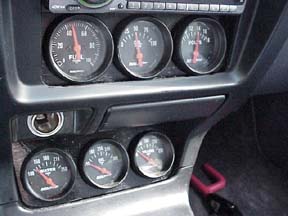
This started me wondering if
the engine was getting enough gas to meet the needs
of the supercharger. I installed an Auto Meter fuel
pressure gauge (see the section on gauges for more
information). What I
saw on this gauge is at about 4-5 psi of boost the
TRD Fuel Management Unit (FMU)would kick in and jump
the fuel pressure up to 65 PSI, so far so good. As
the RPMs continued to climb the fuel pressure would
drop. At the point of maximum demand the fuel
pressure would drop below 50 PSI which is only 7 PSI
over the idle pressure. If you then subtract the
amount of boost from the fuel pressure it places the
actual fuel pressure below the idle fuel pressure
(more on that later).
I spoke to the folks at TRD
about my fuel pressure loss and I was told that the
supercharger only needs 53 PSI for proper operation.
I told them all I was able to maintain was 50 PSI.
The guy had no more answers for me. So, yes, it is
leaning out! I knew I was going to have to fix it my
self.
Back to Index
Boost-A-Pump:

The FMU ups the fuel pressure
so that more fuel can flow from the injectors under
boost. The problem that I saw is that the fuel pump
is not able to flow enough fuel to meet the demands
of the supercharger. As a result as the demand would
go up the supply of fuel would go down causing the
mixture to go lean. This causes the exhaust gas
temperature (EGT) to go way up and power to drop off.
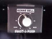
I installed a Kenne-Bell
Boost-A-Pump (BAP). The BAP works by increasing the
voltage to the fuel pump under boost causing it to
spin faster and deliver a greater volume of fuel. The
BAP has a control knob that allows you to adjust the
percentage of voltage increase to the pump. The BAP
is activated by a pressure switch mounted in the
supercharger plenum that activates at 3 PSI of boost.
I adjusted the voltage with the control knob so that
once the FMU kicked in I could maintain the 65 PSI of
fuel pressure. This was 35% on the control knob.
I made a trip to the dyno and
tested the results. I was amazed to see just how much
it increased the HP where without the BAP it would
drop way off. My dyno tests showed that a setting of
35% was ideal for the best power.
I called Mr. Bell at Kenne-Bell
to discuss my results. Mr. Bell was very familiar
with the TRD supercharger and that made things much
easier. He confirmed what I suspected that
supercharger was running lean.
Mr. Bell told me that there is
a very easy test you can do to see if your
supercharger is running to lean or not. Run a tank of
93 octane pump gas and then run your next tank with
100 octane unleaded racing gas. If you see an
increase in performance you are running lean. If the
performance stayed the same you are just right. If
you lost power your are to rich.
Here is what is happening. The
higher the octane the slower the gas burns. The
richer the mixture the slower the mixture burns. The
leaner or the lower the octane the faster it will
burn. Also the leaner it is the more likely it is to
cause detonation. When the engine starts to detonate
the knock sensors picks this up and the ECU retards
the timing. For every degree of timing retard you
loose about 3 HP. When you richen the mixture you are
suppressing detonation and this allows the ECU to run
the timing more advanced so you get better
performance. The BAP allows you to maintain a richer
mixture where before it was leaning out due to fuel
pressure loss.
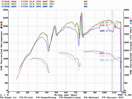
As you can see
there is a very dramatic increase in performance.
These tests where done with the following setup:
K&N FIPK, VPC, and ELP ECU.
The results speak
for them selves. In the second gear pull showed 33.9
HP increase. In the third gear pull where the red
line starts dropping badly there is an increase of
31.1 HP
Exhaust Gas
Temperatures (EGT) where as follows:
Run 4 (BAP 0%)
peak 1655
degrees F
Run 2 (BAP
35%) peak 1579 degrees F
Run 3 (BAP
50%) peak 1577 degrees F
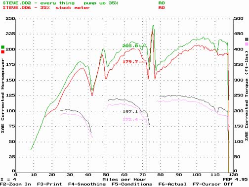
What I found is
that with the BAP the EGT would stay in the mid 1400s
until the very end in each gear where it would
suddenly spike to the temperatures indicated with a
sudden reduction in fuel pressure. It showed up in
the charts as a dip in the line toward the end of
each gear pull. The runs without the BAP the EGT
stayed very close to the peak through out the entire
run.
I installed a digital EGT meter
in the right side exhaust header. This meter has a
recall function and would record the highest
temperature recorded during the dyno run.
I set the BAP to zero for the
first run on the dyno. The dyno operator saw the
incredibly high EGT and aborted the first run. He
then tried to talk me out of any further runs worried
about engine damage. I explained to him that I have
been running it like this for some time and wanted to
press on. He reluctantly agreed.
The run with the BAP set to
zero recorded an EGT of 1655 degrees F. The EGT was
also that high through out the whole run. On the next
run I set the BAP to 35% and the EGT meter showed a
stable EGT in the mid 1400s until just before each
gearshift where it would spike to 1579. On the next
run I set the BAP to 50% and there really was no
additional benefit. The dyno did record a maximum
increase in HP of 33.9 HP with the BAP.
Keep in mind that these runs
were done with the ELP ECU and the VPC that was
already adding extra fuel. I simply can not imagine
what the EGT was without the ELP ECU or VPC.
I do feel much better with the
reduction in the EGT. There is no doubt that my
engine will last much longer.
Back to Index
HKS
Vein Pressure Converter:

The stock air
flow meter is very restrictive. E. L. Prototypes is modifying an HKS Vane Pressure
Converter (VPC) from a Toyota Supra for use on the
3.4L. This unit uses manifold pressure, an inlet air
temperature sensor and a computer to replace the
restrictive stock airflow meter. In place of the
stock air flow meter, a three in pipe is inserted.
After
installing the VPC I noticed an immediate increase in
top end performance. I also found it that it takes a
little time to get the adjustments set so the vehicle
runs properly. Initial setting took about 10 minutes
followed by fine adjustments over the next few days.
Installation
involves:
- Removing
the stock restrictive air flow meter and
replacing it with a straight piece of
pipe.
- Installing
a temperature probe in the plenum. It
replaces a allen headed plug on the rear
of the plenum.
- Installing
a manifold pressure sensor which is
connected to the vacuum line going to the
FMU.
- Splicing
about six wires into the wire harness
coming from the ECU inside of the dash.
- Mounting
the control unit.

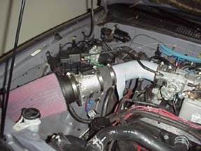
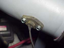
The black box on
the fire wall is the manifold pressure
sensor. The silver thing sticking out of the
gray supercharger plenum is the temperature
probe.
I
installed the control unit in the glove compartment.
I attached it to the roof of the glove compartment.
This works out real nice. It is out of sight unless
you stoop down and look up and provides easy access
to the controls.

The
VPC Control unit has four knobs: Response (works
like an accelerator pump), Gain (overall
mixture), Idle (idle mixture). The fourth knob is
the "Option Out" knob. This is for
piggy back HKS computers like the F-Con, or the
GCCII. It is not used in my application.
There is a
hesitation that remains after setting all the
adjustments. This hesitation only occurs when pulling
off from a complete stop with a rapid throttle input.
I have tried everything possible to reduce the
hesitation. I spoke to Eric at E. L. Prototypes and
he agrees that it is most likely a slight bug in the
program. Eric has sent me a total of four different
chips and still the hesitation remains.
I have upgraded
my fuel injectors and because I have not been able to
get a new program to properly control the injectors
from E. L. Prototypes, I have had to replace the VPC
with a Split Second unit.
Back to Index
Injector
Upgrade:
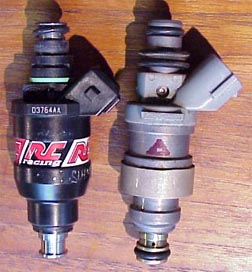 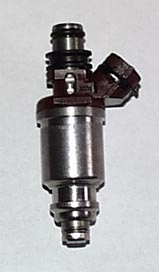
Left
is the 270 cc Lucas injector, center is the stock 238
cc injector, and right is the 305 cc Toyota injector.
It was clear that I still was
not getting enough gas into the engine. Remembering
back to my first set of dyno runs the dyno operator
told me I needed an injector upgrade. He pointed out
the jagged saw tooth look to the lines on the chart
and said every time he has seen this it ended up
being to lean.
I sent one of my stock
injectors to RC Engineering and had it flow tested. It flowed at
238 cc. That means that when locked full open it will
flow 238 cc of fuel per minute. Locked full open is
100% of its duty cycle. The maximum recommended duty
cycle of any injector is 80%. This is the industry
standard to prevent erratic injector operation.
I used the fuel flow formulas
on the RC Engineering web page and computed the max HP for
the stock injectors out of my truck. At 80% duty
cycle they will support 198 HP and at 100% they will
support 247 HP. The 198 HP seems real bad and the 247
sounds a little more acceptable if the ECU will run
the injectors at 100% duty cycle.
I called E L Prototypes and
spoke with Eric the owner about my project. He told
me that he had just installed injectors out of a 95
GS300 in his drag 4Runner. He had developed a new
chip for the VPC he is marketing that would control
the GS300 injectors. He said he would send me the
chip to try out and if needed make me a new chip
specifically for my size injectors.
I ordered the 270 cc Lucas
injectors from RC Engineering. To install them I had to modify the
wire harness connectors as the Lucas injectors use a
different plug. At this I had previously removed the
HKS VPC due to drivability problems and was hoping
the ECU was capable of handling the new injectors by
its self. The ECU could not control the new injectors
effectively and tripped a check engine light.
I reinstalled the HKS VPC with
the new injector chip. The chip was for injectors
that where bigger and it ran to lean. I switched back
to the original chip and it ran to rich. I called
Eric and he said he would make me the chip I needed.
Eric has many projects in the works and it was taking
forever.
I was asked to try the Split
Second MAF conversion
kit. I installed the unit and was really impressed.
It dialed in the injectors nicely.
The 270 cc injectors really
made a big difference. It was making lots of power
and the EGT was way down. The problem I was now
having was with the TRD FMU that came with the
supercharger kit. With the FMU connected it would run
to rich at times due to the large rise in fuel
pressure. With it disconnected it would run to lean.
Thats right it would run to lean with 270 cc
injectors without the FMU. You folks with stock
injectors and no FMU on your TRD supercharger better
re-read that a few times.
After a long talk with Mr. Bell
at Kenny-Bell superchargers I was convinced that all
forced induction engines needed an FMU of at least
1:1 ratio. See the FMU section on this page for more
information on FMUs. I knew I needed an FMU but I
also knew that the 270 cc injectors are not big
enough for a 1:1 ratio FMU. I needed still larger
injectors.
I did some math and figured that a fuel
injector in the range of 300-320cc would be the perfect size
injector for my needs. I looked at different Toyota
applications and learned that the 95 GS300 used a 305cc
injector. I obtained a set and had them flow tested and they
were 305cc. Toyota
dealerships and they provided me with a Toyota part
number of 23209-46031 and said
this is the same injector used in the following
applications:
- 93-98 Toyota Supra
NON-turbo
- 94-97 Lexus SC300
- 93-94 Lexus GS300
California Emissions
- 93-97 Lexus GS300
Federal emissions
There is a guy (I am not going
to use his name so he will not get into trouble) I
know that works in one of the Toyota parts
distribution centers and I was able to get two sets
of these injectors at dealer cost. It was a one-time
deal. One set was for Ron S one for me. I sent the
injectors to RC Engineering and had them flow tested. They flowed
at 305 cc. I was kind of disappointed that they were
not 330s and was told by RC Engineering that
Eric’s injectors were flow tested at 312 cc.
I went ahead and installed
them. I also installed a Cartech model 20005 FMU that is completely
adjustable for onset and rate of rise so I could test
different fuel pressures to determine the ideal fuel
pressure for these injectors.
The first test drive showed I
had the perfect size injectors for my truck. I was
able to back down the FMU down to as close to a 1:1
ratio as I could get and the injectors were working
just fine. I was able to tune the Split
Second so that it idled
fine and at full boost I was able to get the EGT
right at 1400 degrees F. My prior dyno testing showed
that this EGT was the best power for my engine. With
this EGT my air/fuel ratio meter was indicating a
ratio of 13.2:1 as indicated by the first blue light
solidly lit on my Split
Second air/fuel ratio
meter.

Split Second ARM1
I called Magnuson Products, the people that make the supercharger
kit for TRD and they confirmed the ideal EGT for this
engine at max boost is 1400-1450 degrees that made me
feel great. I then called Split
Second and to talk to
them about the best air/fuel ratio. Split Second has
been doing some development work for TRD by the way.
They confirmed that the air/fuel ratio that I was
running is ideal for my application. So I feel very
confident that I have exactly the right size
injectors for my truck.
I do not see any need to go any
bigger. I have the high control on the Split
Second dialed way back
so I think that there is still plenty of room left in
these injectors. I wish I had a duty cycle tester to
see at what percentage of the maximum duty cycle on
the injectors are at full boost.
I also think that my 270 cc
injectors would work if I used them with the tunable Cartech FMU. It may just be a matter of finding
the ideal ratio of fuel pressure to boost pressure. I
know that with the TRD FMU it would be to rich at
times so that would indicate that it is possible to
flow enough fuel from the 270 cc injectors with the
proper fuel pressure rise. I think I will leave that
to someone else to iron out.
So if you want to do what I
have done you do have a few options depending on the
money you want to spend. The first is choosing the
injector. The Toyota injectors that I am using will
snap right into the wire harness without any
modifications, but cost much more then the 310cc
Lucas injectors from RC
Engineering. So if you
are trying to watch your money I would have to say go
with the RC Engineering injectors. You also may be able to find
some used Toyota injectors out one of the vehicles
listed above. Before you install them make real sure
the coil resistance is 13.8 ohms. Toyota uses
injectors with different coil resistance and you must
use high impedance injectors of about 13.8 ohms or
you may smoke your ECU.

Split
Second ARC 1

Split
Second ARC 2
You will also have to use some
type of injector driver or controller. I am using the
Split Second 3" MAF conversion kit with an ACR2
controller. That will cost you around $1100 and replaces the stock air flow meter
(AFM). You can go a cheaper route and get the Split
Second ARC1 controller
which is designed to work with the stock AFM and
costs around $300. You can later upgrade to a Supra
AFM for more airflow and more power. For information
on the Split Second ARC1 go to the Split
Second web page and
down load their brochure.
Back to Index
Split
Second Unit:

I obtained one of Split Seconds MAF conversion
kits and installed in on my 96 4Runner. A custom air tube had
to be made.
This
is what the prototype installation looks like. I can
not wait to see the final version. JT says he is
making the production version out of spun aluminum.
I have been running upgraded injectors for some time and have been trying to
get a new chip for my VPC that was tuned for my new
injectors. Eric at E
L Prototypes has sent
me a total of four chips for my VPC and
none of them were quite right. Given time I know that
he will eventually nail it, but the problem with the
VPC is that any time you change something you have to
have a custom program done to match it. With the SS
you just dial in the needed changes with the control
panel and you are all smiles.
The vender I got the kit from sent me a wiring
guide that was totally wrong and I had to sort all that out
myself. After sorting out the
wiring connections I had the Split Second installed
and running. I went on a test drive and was simply
amazed on the difference in performance. The throttle
response was incredible as was the top end power.
Simply by snapping the throttle
I can break the rear tires loose at will. Low end,
mid range and top end response and performance is
simply perfect. This is the one modification that has
brought all of the others together.
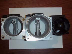
This
is a picture of the three different AFMs side by
side. Left is the SS 3", middle is the SS
3.5", and the one on the right is the
restrictive stock AFM. You can see why the stock one
is so restrictive. That big thing in the middle
really cuts down on the space that air can flow
through.
I prefer
the stock airbox over the cone type filters mostly
for the noise reduction and I know the K&N type filters are
about the worse air filter on the market for filtration. The cone type filters is
very loud. Once I get it I will test everything on
the dyno and report the results.
I am sorry to
say that even with my 270 cc injectors I still can
not get enough gas into the engine to prevent a lean
condition without the FMU connected. More proof that larger
injectors are needed.
I
used an air temp sensor out of a Nissan to substitute
for the one that is built into the stock AFM that I
removed.
The stock AFM has
the induction air temp sensor built into the unit.
When the stock AFM is removed the stock air temp
sensor goes with it. JT takes the same approach that
Eric at E L Prototypes did with the VPC. He includes
a resistor that is spliced into the stock AFM
harness. This resistor tells the ECU that the
induction air temp is at 68 degrees all of the time.
I decided to see if I could find a replacement air
temp sensor that I could use as a substitute. Using
the voltage values listed for the stock air temp
sensor listed in the Toyota shop manual I set out
testing all the air temp sensors I could find. I
found that the induction air temp sensor on my 95
Maxima was a perfect substitute.
I visited the
Nissan dealer and found that new ones are $65. I went
to visit my friend at the junk yard. I got four used
ones and brought them home and started to test them.
Out of the four two were still good. I sent one to Ron and
installed the other in the prototype air tube and
spliced it into the harness.
I can not say that
I have noticed any difference at all over the
resistor, but I do feel better knowing that the ECU
is now receiving the proper data to make its
calculations from.
I spent some time
prowling the junk yards and picked up a flanged
3" composite AFM and a air tube from the 99 Ford
Crown Victoria. I cut everything off of the rear of
the stock air box and the air flow meter was a
perfect fit if it was turned upside down. I then
sealed it with silicone. I then cut down the air flow
tube and I also cut down the metal tube. Everything fit real nice and
looks as if was OEM. I transferred the electronic module from the 3.5" Split Second AFM to the
Ford AFM. The bellows in the air tube provide plenty
of stress relief to allow for engine movement.
With the opening I cut in the front of my air box this setup emits a very pleasant hum
from the front of the vehicle at idle. What I like
most about this set up is that it is very, very
quiet. I wanted to get away from the K&N cone filter for its lack of
filtration and the
noise it makes.
Although this todate was the best
setup I had installed, the ARC2 controller just did not have enough
precision for optimum tuning and it was removed along with the
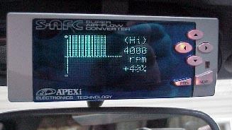
MAF. I then went back to the stock MAF and used the APEX S-AFC
for a controller.
Back to Index
Apex
Super AFC:
I currently have
the AFC installed above my rear view mirror. It is easy to
tweak
it at stop lights. I am planning to move it to the glove
box soon.
There is a new device on the
market that works like the Split Second ARC units. It is made
by APEX and it is called the Super AFC. It operates on the
same concept as the SS ARC units by modifying the signal from the
MAF. By doing so you can alter the fuel mixture and dial in
larger injectors.
The thing that makes the AFC
different from the SS is that you can make the air flow corrections
at specific RPM and throttle settings and that can not be done with
the SS units.
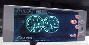
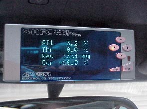
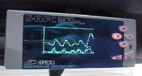
The AFC is a very small compact
unit that makes installation much easier. It also has all
kinds of data displays like RPM, correction factor, throttle
position, air flow, and a few others.
I really liked how easy it was to
tune in. I had removed the Split Second stuff and replaced it
with my stock MAF and the AFC. The truck ran really good with
this combination, but I did loose some top end power with the more
restrictive stock MAF.
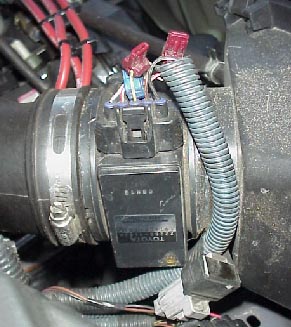
The Supra MAF is
easy to adapt to the stock airbox.
Because the mounting holes are on the opposite side as on the
stock MAF, I had to rotate it 90 degrees to the passenger side.
The nice thing is that it just plugs in to the stock harness.
It also has the IAT built in just like the stock one.
I was able to obtain a used MAF from a twin turbo Supra. It is
very much like the stock MAF on my 96, but much, much bigger.
It is very easy to adapt it to the stock air box. With the
larger MAF all the top end power came back. Overall I liked
this combination so much I sold my ARC2 and 3.5" SS MAF.
With the stock MAF and my 305cc
injectors, I had the low throttle settings on the AFC set at -15%
and the high throttle settings at -10%. The hot wire type is
set to 01 and 01. Works really nice.
I had to retune the AFC when I
upgraded to the larger Supra MAF. The low throttle settings
are, +20% and the high throttle settings are +35% and +40% at 4000
RPM and up. The hot wire type is set to 15 and 15. As
you can see with the larger Supra MAF the settings must be much
higher to compensate for the greater air flow through the larger
MAF.
The AFC is really popular in the
sport compact car scene and they can be hard to find. You can
shop around on the net and find one at a good price.
HKS has come out with a similar
unit called the AFR. I have made connection guide for several
people that got the HKS AFR and most all of removed them and
replaced it with the AFC. There is no graphic display and it
seems that people loose track of where their settings are. I
suggest that if you get one you plot your correction factors out on
some graph paper so you have something visual to look at during your
tuning. To date I know of one person that was successful in
getting the AFR properly dialed in, most of the rest hated it.
I have since removed the AFC and
upgrade to the Split Second Fuel Timing Calibrator (FTC).
Back to Index
Fuel
Management Unit:
TRD includes, or at least did,
a Fuel Management Unit (FMU). In theory what this
thing does is increases fuel pressure under boost to
cause more fuel to flow from the injectors.
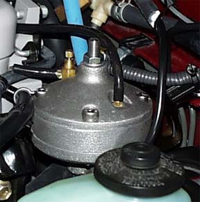
The TRD unit is installed by
removing the stock fuel pressure regulator from the
fuel rail. The TRD FMU is then clamped on top of the
stock fuel pressure regulator. The FMU has a
diaphragm in it that is deflected by positive
pressure in the manifold (boost). There is a pin
attached to the diaphragm that pushes on the
diaphragm in the stock regulator causing it to hold a
higher fuel pressure then it normally would. The
combination FMU/regulator is bolted to the firewall
and the stock regulator is connected to the fuel rail
with a high-pressure hose. A vacuum hose connects the
FMU to the supercharger plenum.
By increasing the fuel pressure
you are forcing more fuel from the injectors into the
engine. Is this a Band-Aid fix for not having
injectors big enough to do the job, or does the FMU
just allow you to brake even?
I spent some time talking to
Mr. Bell at Kenne-Bell about supercharger fuel needs.
Mr. Bell is a wonderful guy and he is a real straight
shooter. It is his opinion that all forced induction
engines must have an FMU of at least 1:1 ratio of
boost to fuel pressure increase. He explains that if
your normal fuel pressure is 43 PSI and you increase
your boost is 7 PSI with no FMU you have a negative
affect on the fuel pressure and are essentially
reducing the fuel pressure by 7 PSI. As the pressure
increases in the plenum it restricts the fuel from
flowing from the injectors. In this example you have
a net affect on the fuel pressure by a reduction of 7
PSI so it is now 36 PSI. This further compounds the
lean condition. By the way TRD does in fact sell a
1:1 FMU as an upgrade for the turbo Supra.
Interesting don’t you think?
Here is the problem. Stock fuel
pressure regulators and fuel pressure gauges work by
comparing the fuel pressure in the fuel rail with the
pressure of the OUTSIDE air and not the pressure in
the manifold or plenum. This is fine for a normally
aspirated engine because the manifold pressure never
exceeds the outside or atmospheric air pressure.
Forced induction engines are different. As the
pressure in the plenum increases it has the affect of
decreasing the fuel pressure by the same amount
because it makes it harder to flow fuel from the
injectors into the plenum. This is where an FMU comes
in. It will adjust, or supposed to anyway, the fuel
pressure in relation to the pressure in the plenum.
A big problem that I have
observed with the TRD FMU is that it is very
inconsistent. If I quickly apply the throttle the TRD
FMU reacts very quickly and jumps up the pressure. If
I ease into the throttle the TRD FMU dose not react
until I get about 5-6 PSI of boost. This maybe why
some 4Runners ping under light acceleration. The
overall amount of fuel pressure increase is very
inconsistent and does not seem to have a good
relation to the boost pressure. In other words it is
erratic as hell. As the boost goes up fuel delivery
is being reduced until the TRD FMU kicks in.
TRD has deleted the FMU from
the newer supercharger kits. We have been told that
this was done to eliminate pinging on the 98 and
later models. From my testing and the very high EGTs
even when using the FMU, the thought of running the
supercharger without an FMU is real scary at best. I
wish TRD would replace the erratic FMU with a more
stable and consistent one instead of just getting rid
of it.
Ron has installed a Cartech FMU
that allows him to adjust the ratio of fuel pressure
increase in relation to boost pressure and the onset
of the increase. What that means is it can be
adjusted to a 1:1, a 2:1, a 5:1 or what ever you
want. Not only that, but you can adjust it as to when
the increase in fuel pressure starts. You can set it
to start as soon as you have boost or what until you
reach a certain boost level. Ron had such great
results that I decided to order one so that I could
test different fuel pressures with my new injectors.
The Cartech FMU is different
then the TRD FMU. It is not installed on top of the
stock fuel pressure regulator like the TRD one.
Instead it is installed in the fuel return line that
returns fuel from the regulator to the fuel tank. The
way this FMU works is that it restricts the fuel
leaving the stock regulator when needed to increase
fuel pressure in the fuel rail.
This FMU is ideally suited for
installation on the TRD supercharger kits with the
deleted FMU, or to replace the erratic TRD FMU. The
only thing is that you will have to replace the fuel
return hose from the regulator to the tank with a
section of high-pressure hose. Ron came up with the
idea of upgrading this hose is when the supercharger
is being installed. Because the newer kit do not
remove the regulator from the fuel rail the only way
to get to it is with the supercharger off of the
engine. Everyone installing the supercharger should
plan ahead and replace the return hose with a
high-pressure hose at the time of supercharger
installation. This way if you decide to install the
Cartech FMU after installation you will not have to
remove the supercharger to do so.
It is important to keep in mind
that there is no way a FMU can make up for the
injectors being to small. On the RC Engineering web
page Russ has an example using a 240 cc injector. By
upping the fuel pressure from 43 PSI to 50 PSI there
was an increase of only 2.64 HP worth of fuel flow
for that injector. Now if you subtract out the boost
pressure differential of say 7 PSI of boost you
really have accomplished nothing and really only
broken even.
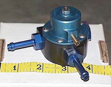
Cartech
20005 FMU
I installed the Cartech 20005
FMU along with my new 305 cc injectors. I was hoping
that I would only need a 1:1 ratio of fuel pressure
rise to boost pressure. My tests confirm that with my
new 305 cc injectors a 1:1 ratio is ideal. I have
found that the Cartech FMU is a very nice unit and is
very consistent and reliable and will give the same
results time after time. It performs as it should and
not like the erratic FMU that was included with the
TRD Supercharger kit. Those of you that are still
running stock injectors and no FMU this would be a
good one for you to get. It installs in the fuel
return line from the stock fuel pressure regulator.
You will need to upgrade the line from the stock
regulator to the Cartech FMU with a high pressure
fuel injection hose as the stock return line is not
intended to hold pressure.
TRD
Supra fuel pressure regulator (FMU)
Now that I have confirmed that
a 1:1 ratio is ideal with the 305 cc injectors, I
replaced my Cartech FMU with this TRD fuel pressure
regulator. It is suposed to work just like the
Cartech FMU and is fixed at a 1:1 ratio. I installed
it and found out real fast it really is not any good.
I set it up just like the
Cartech FMU. I adjusted the onset screw with the
vacuum line disconnected from both the stock fuel
pressure regulator and the TRD fuel pressure
regulator so I noticed the slightest increase in fuel
pressure above the stock regulator. Then I locked the
jam nut.
I went for a test drive and
found that it does not provided a 1:1 ratio increase
in fuel pressure at all. It would increase fuel
pressure about 3 psi at the most. So with 9 psi of
boost indicated it would only increase fuel pressure
by 3 psi. It was not any good for my purpose and I
removed it and reinstalled my Cartech FMU until I
discovered the "FREE FMU".
Overall, I have had little luck using these
FMUs. They all proved erratic, inconsistent and totally
worthless. I am convinced that all these pressure increasing
FMUs are junk and are nothing more then a piss poor band aid
fix. The proper thing to do is to install the correct size
fuel injector and control them electronically.
Free FMU:
While testing the Cartech FMU
and the TRD Fuel pressure regulator I decided to see
if I could run my 305cc injectors without an FMU
stumbled across something. I removed the Cartech FMU
and went for a test drive. I was surprised to see
that my fuel pressure was increasing when I was in
boost at a ratio of 1:1. How can this be?
I checked out my connections
and found that I had the stock fuel pressure
regulator (FPR) hooked to the boost port. The stock
connection is to the main air induction tube which is
really nothing more then a vent and gives a constant
43 PSI all the time.
With the FPR hooked to the
boost port it will react to boost pressure and
increase the fuel pressure under boost at a perfect
1:1 ratio. This offsets the boost pressure
differential that I discussed earlier and really does
a good job of stabilizing the fuel pressure in
relation to manifold or boost pressure. The funny
thing is that all the other fuel injected engines I
have toyed with has the FPR connected to a port that
allows it to read and adjust the fuel pressure in
relation to engine load (manifold pressure).
Here is the benefit with the
TRD supercharger. Like I explained earlier, as the
manifold pressure increases in boost it will restrict
fuel flow from the injectors. By reconnecting the FPR
to the boost port you prevent this problem and it
will give you 6-7 PSI of extra fuel pressure at max
boost that you did not have before. Many people with
the dreaded pining problem have tried this and it has
in some cases eliminated the high gear, low RPM ping.
All have reported an improvement.
I do not think for a second
that this will be enough to prevent the fuel system
from leaning out at max boost, but it will not be as
bad.
Give it a try. It is FREE and
you can easily switch it back. I have been told that
TRD has heard about my little trick and is now
recommending it as their own discovery.
I currently have my stock FPR
connected to the boost port and I am using the 305 cc
injectors.
Back to Index
Split Second ESC1:

With the larger injectors and
the Split Second (SS) ARC2 controller I have solved
my top end fuel delivery problems. There was still
one spot in the power band I was not happy with. That
was part throttle acceleration under boost. In this
region I felt that the engine just was not producing
the power it should and there was a constant surging.
I figured out what was causing
the surging as soon as I installed my SS air/fuel
ratio gauge (ARM1). It is from the ECU operating in
"closed loop" operation. In closed loop
operation the ECU it constantly adjusting the fuel
mixture to try to find the "ideal" mixture.
The mixture is being varied from rich to lean, then
back to rich. This cycle takes about a second to
complete. When it is on the rich side there is more
power, when on the lean side there is less. So it
presents as surging in power. More proof that this
engine control system was not intended to support an
aftermarket supercharger.
At full throttle the ECU
switches into "open loop" operation and it
is no longer cycling the mixture. It switches over
and uses the full throttle fuel map, which is richer
then cruise power and it makes more power. It would
also switch into open loop if I continued to
accelerate in 3rd gear for about seven seconds or
more. As soon as it would switch into open loop the
surging would disappear and there would be a
noticeable jump in power.
I found I could adjust my SS
ARC2 so that it would be real rich in the mid range
while acceleration under boost with part throttle.
This would cause the ECU to switch into open loop and
would run nice in this narrow range, but would throw
everything else way out of adjustment. I knew what
had to be done, just not how to do it. I started
making calls and spoke to Eric at SS. He said that
they had just the thing I needed, the ESC1.
The ESC1 is a signal
conditioner. They make a few different ones that
modify the signal from the sensors to the ECU. This
one modifies the signal from the front O2 sensor.
Under boost it modifies the signal from the O2 sensor
to the ECU causing the ECU to switch into open loop.
There are 4 wires that get
spliced into the ECU harness, and a vacuum line that
is connected to the boost port. I found that the
connections have to be made behind at the ECU, which
it located behind the glove box. The O2 sensor wires
are shielded in the engine compartment to prevent
interference so you can not make the connections
there. I originally installed the ESC1 behind the
glove compartment. I had a loud buzz under boost. It
turned out to be whine from the supercharger
traveling up the vacuum line. I then followed a
friends lead and installed the ESC1 on the firewall
next to the wiper motor.
I went for a test drive and
found out right away, this thing is great! Shortly
after going into boost the ECU kicks into open loop
and I now have so much more power then I did before
at the lower boost levels. The surging is GONE. Now
for the very first time my supercharger feels like a
factory installed unit. It is very smooth and very
torquey at lower boost levels. It is amazing what
just a tad more fuel will do for the drivability of
the supercharger.
I live off of a long country
highway with lots of hills. Using the cruise control
was impossible due to all the downshifting. The
installation of the supercharger made that a lot
better, but it still down shifted more then I liked.
Now with the SS ESC1 the engine makes so much more
torque at highway speeds it no longer down shifts. It
climbs the same hills with 2-3 PSI less boost then
before. It is interesting to watch the boost gauge
suddenly drop 2-3 PSI as soon as the ECU transitions
into open loop.
I find that I can pass the slow
pokes hogging the left lane and that are too rude to
move over without down shifting. I just ease in the
throttle and get lots of torque and I can add 20 MPH
without down shifting so fast it feels like I have a
350 in it.
So, the SS ESC1 gets my seal of
approval. It works and does exactly what SS says it
will do. The ESC1 will work on all O2 sensor equipped trucks from
95-98. Starting in 99 Toyota started using an wide band O2
sensor on some truck and the ESC1 is not compatible with that
sensor. Still some trucks were equipped with the old style O2
sensor, but there is no boost induced power surging on the 99 and
later trucks so I do not recommend using the ESC1 on anything newer
then 98.
Back to Index
Final
Recomendations:
Fuel delivery solution has to
be done in a package deal. One thing without the
other is only a half assed approach. The first thing
is everything is dependent on there being enough fuel
available from the pump in the first place. You
should install a BAP or a larger pump so that enough
fuel will be available. I am using the BAP. Then you
have to find a way to get it into the engine. I have
chosen to install adequate fuel injectors. Another
approach is to install extra injector(S) in the
intake track. Then there must be a way to properly
control the injectors so the right amount of fuel is
injected at the right time. I am using the Split
Second Unit. And lastly you must make sure that boost
pressure is not going to restrict fuel flow from the
injectors by installing an FMU.
You also must be able to
monitor engine operation to make sure everything is
working properly. I did this by installing a Split
Second Air/Fuel ratio meter, a dual EGT gauge, and a
fuel pressure gauge. This allows me to cross check
engine functions and be able to spot a problem before
I melt a piston.
After everything I have learned
from my dyno testing I have developed the opinion
that the TRD supercharger kit runs to lean. I have
discussed my findings with several other supercharger
kit manufacturers and all have agreed with my
findings. The real kicker was a guy that worked for
the company that developed the TRD kit for TRD. He
says that he had told TRD that the kit in it current
form without the TRD FMU is to lean and that TRD has
flat out chosen to ignore him. He said, "it is the
most expensive way I have ever seen to aluminize an
exhaust system."
Update:
I have formed a company to market a fuel kit
based on everything I have tried, learned and developed to
date. This is a complete kit that includes everything needed
to solve the High RPM Lean Out problem, the HG/LR-ping, as well as
provide a very nice increase in performance.
I installed one on a 2001 Tacoma and dyno
tested better then a 40 HP gain.
Check it out at www.URDUSA.com.
Back to Index
|